Isochronous Governor & Droop Characteristics
 |
| Isochronous Governor |
An isochronous governor is the speed control system designed to
operate in a single unit of generating plant supplying isolated load. This type
of governor is not suitable for the power system with multiple generating
units.
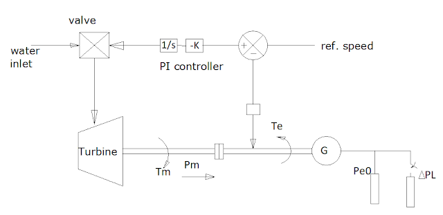
Figure shows the schematic diagram of the isochronous
governor. When the system is operating at steady state condition, then
mechanical power input Pm0 is equal to electrical power output Pe0
and speed remains constant at w0.
At time t=0, the electrical load ΔPL is switched on and then the mechanical power
will be less than electrical power and hence the speed decreases as shown
above.
Now the speed sensor senses the change in speed and compares
with reference speed thus producing the error signal Δw. Then PI controller produces control signal Δy which makes the certain opening of gate.
Due to opening of gate, mechanical power increases and at
point p, it becomes again equal to electrical power output. But, due to
rotational inertia, the mechanical power cannot stay at point p. Hence,
mechanical power increases beyond point p.
Due to increase in the mechanical power after point p (which
is corresponding to speed at point A), speed also start to increases and
reaches to steady state speed w0.
At time t=t1, mechanical power is again equal to
electrical power output and this time, Pm =Pm0 + ΔPL, becomes stable and system attains steady
state.


0 Comments