Speed Governor and its Modeling
 |
| Speed Governor |
Speed governor is the automatic control system that controls
the speed of the turbine-governor according to the load condition. The block
diagram of the speed governor is shown above.
Tm = mechanical torque produced by turbine.
Pm = mechanical power input to the generator
Te = electrical torque that opposes the mechanical
torque.
Pe = electrical power output
At steady state, Pm
= Pe
Also, Tm = Te ; at constant
speed w0
In the absence of the speed generator, the turbine-generator
coupled system shows tendency to control the speed due to load variation to
some extent and it is due to inertia. Mathematical expression can be generated
during transient period, due to change in electrical load, the acceleration of
deceleration of the shaft is given from
law of motion as;
dw/dt = 1/2H×(Tm – Te ) ----------------(1)
where,
H=inertia constant of turbine generator coupled system.
lets replace d/dt operator by ‘Δs’ in laplace domain
s.Δw = 1/2H× (Tm – Te)
Or, Δw= 1/2Hs×((Tm – Te) ---------------------(2)
Equation 2 can be represented by
following block diagram:
 |
| speed control by inertiaTurbine-Generator coupled system |
If change in
the electrical load is significantly very large then the inertia of the
turbine-generator system not sufficient to control the speed. In this case, a
automatic speed governor is used
For a
rotating system, power can be related with the speed as:
P = wT -------------------------------------(3)
Considering
small change in power, speed and torque as ΔP, Δw, and ΔT respectively. Then equation 3 becomes:
P+ΔP = (w0+Δw)(T0+ΔT)
P+ΔP
= w0.T0 + w0.ΔT + Δw.T0+Δw. ΔT
ΔP
= w0. ΔT + Δw.T0
Since, ΔP = ΔPe - ΔPm
So, ΔPe - ΔPm =
w0.( ΔTm – ΔTe) + Δw(Tm – Te)
At steady state; Tm = Te
ΔPe
- ΔPm = w0. ( ΔTm – ΔTe)
In pu system,
when base speed is equal to initial speed, then w0 = 1 pu.
ΔPe - ΔPm = ( ΔTm
– ΔTe)
In general,
power system loads are composite in nature. Which is mixture of both resistive
and inductive loads.
Inductive
loads are frequency dependent. The frequency dependent loads produce damping effect to control the
speed. Hence in general, power system loads can be represented as:
ΔPe = ΔPL + D. Δw
ΔPe = ΔPL
+ D. Δw
Where, ΔPL = frequency independent load
And D. Δw = frequency dependent load whose
effect comes into account only during transient period.
Where, D = load damping constant.
Load damping constant is defined as
the % change in load for 1% change in frequency.
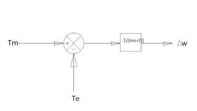
If we include the effect of load
damping constant ‘D’, the block diagram will be:
 |
block diagram of speed governor with damping constant 'D'
|
The final Block Diagram of governor Modeling is:
 |
| The final Block diagram of Governor modeling |


0 Comments